mail_outline sales@mediastorehouse.com
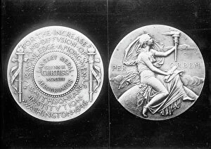
Langley Medal presented to aviator Glenn Hammond Curtiss, 1913. Creator: Harris & EwingLangley Medal presented to aviator Glenn Hammond Curtiss, 1913. Glenn Hammond Curtiss was the manufacturer of the Curtiss Airplane
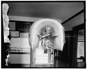
Model airplane, between 1910 and 1920. Creator: Harris & Ewing. Model airplane, between 1910 and 1920Model airplane, between 1910 and 1920. USA. Scientific apparatus with propellers
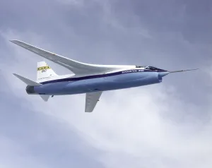
NASA F-8A Crusader Supercritical Wing Aircraft, 1973. Creator: NASANASA F-8A Crusader Supercritical Wing Aircraft, 1973. A Vought F-8A Crusader was selected by NASA as the testbed aircraft (designated TF-8A)
Linear Aerospike SR-71 Experiment (LASRE), USA, 1997. Creator: NASALinear Aerospike SR-71 Experiment (LASRE), USA, 1997. A NASA SR-71 successfully completed its first flight October 31, 1997 as part of the NASA/Rocketdyne/Lockheed Martin Linear Aerospike SR-71
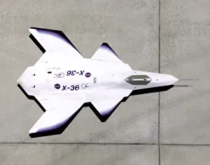
X-36 on ramp, USA, 1997. Creator: NASAX-36 on ramp, USA, 1997. NASA Dryden Flight Fesearch Center at Edwards Air Force Base in California hosted the X-36 program, as well as providing range support for the flight tests
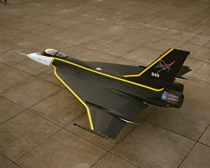
F-16XL with custom paint, USA, 1993. Creator: NASAF-16XL with custom paint, USA, 1993. On October 5, 1993, Langley Research Centers F-16XL High Lift jet was rolled out with a dynamic yellow
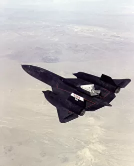
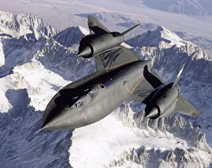
SR-71 over snow-capped mountains, USA, 1995. Creator: NASASR-71 over snow-capped mountains, USA, 1995. Drydens SR-71B, NASA 831, slices across the snowy southern Sierra Nevada Mountains of California after being refueled by an Air Force Flight Test Center
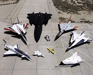
Dryden research aircraft fleet on ramp, USA, 1997. Creator: NASADryden research aircraft fleet on ramp, USA, 1997. A collection of NASAs research aircraft at the Dryden Flight Research Center in California: X-31, F-15 ACTIVE, SR-71, F-106, F-16XL Ship #2, X-38
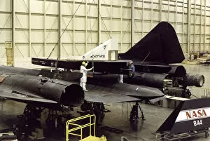
LASRE Pod Matting to SR-71, USA, 1996. Creator: NASALASRE Pod Matting to SR-71, USA, 1996. View of the Linear Aerospike SR Experiment (LASRE) pod on NASA SR-71, tail number 844. This photo was taken during the fit-check of the pod on Feb
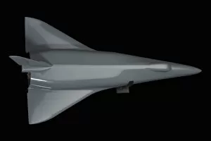
Model, Space Shuttle, Delta-Wing High Cross-Range Orbiter Concept, 1970s-2000s. NASA used this Space Shuttle orbiter concept model in wind tunnel tests to learn about the flight characteristics of
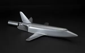
Model, Space Shuttle, Straight-Wing Low Cross-Range Orbiter Concept, 1970s-2000s. NASA used this Space Shuttle orbiter concept model in wind tunnel tests to learn about the flight characteristics of
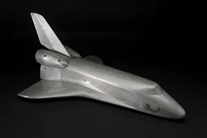
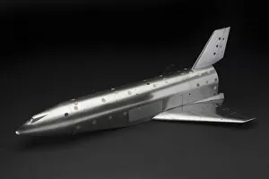
Model, Space Shuttle, Final Orbiter Concept, 1970s-2000s. Creator: UnknownModel, Space Shuttle, Final Orbiter Concept, 1970s-2000s. NASA used this Space Shuttle orbiter concept model in wind tunnel tests to learn about the flight characteristics of the vehicles shape
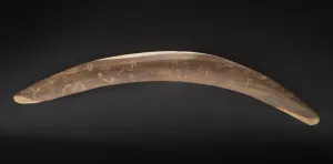
Boomerang, ca. 1969. Creator: UnknownBoomerang, ca. 1969. This boomerang, an example of the " first aerodynamic shape conceived by man, " was presented in 1969 to NASA astronaut Michael Collins by the Australian Television
Model, Wind Tunnel, Convair Space Shuttle, 2007. Creator: General Dynamics CorporationModel, Wind Tunnel, Convair Space Shuttle, 2007. This wind tunnel 0.006 scale model set dates from the early Space Shuttle design effort
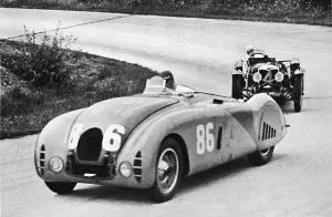
French Grand Prix, 1936: A new streamlined Bugatti, followed by a Riley, 1936, (1937). From Sir Malcolm Campbells Book of Famous Motorists, edited by Sir Malcolm Campbell
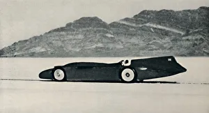
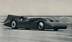
Over 300 miles an hour on the Salt Flats, Bonneville, Utah, 1937. From Sir Malcolm Campbells Book of Famous Motorists, edited by Sir Malcolm Campbell. [Blackie & Son Limited, London and Glasgow, 1937]
276 miles an hour on the sands at Daytona, 1937. From Sir Malcolm Campbells Book of Famous Motorists, edited by Sir Malcolm Campbell. [Blackie & Son Limited, London and Glasgow, 1937]
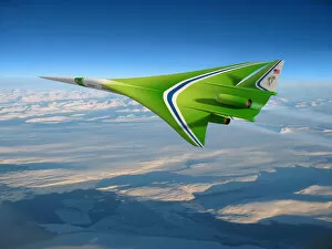
Updated Supersonic, USA, 2007. Creator: NASAUpdated Supersonic, USA, 2007. Aircraft design concept from NASA research partner Lockheed Martin, a good example of how simulations and wind tunnel tests, conducted over time
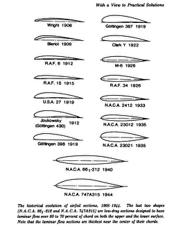
Evolution of the airfoil, 1908-1944. Creator: UnknownEvolution of the airfoil, 1908-1944. Diagrams showing the historical evolution of airfoil sections. The last two shapes are low-drag sections designed to have laminar flow over 60 to 70 percent of
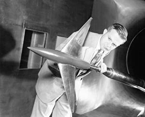
Richard Whitcomb with Area Rule Wind Tunnel Model, USA, April 20, 1955. Creator: UnknownRichard Whitcomb with Area Rule Wind Tunnel Model, USA, April 20, 1955. Aviation pioneer Richard Whitcomb worked at the Langley Research Center in Virginia throughout his exceptionally prolific life
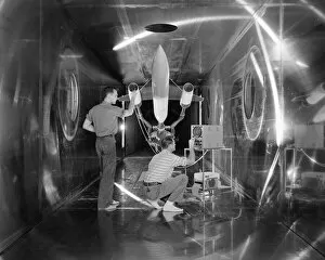
Engineers check body revolution model, Ohio, USA, July 31, 1957. Creator: UnknownEngineers check body revolution model, Ohio, USA, July 31, 1957. Engineers at the Lewis Flight Propulsion Laboratory making a check on the body of a model of a supersonic aircraft before a test run